Theoretical & Physical Foundations
Rigorous aerospace and naval engineering principles underpinning each subsystem.
Principle 01
Oleo-Pneumatic Shock Dissipation (Jumbo Jet Architecture)
The tri-cylindrical nested suspension system (Upper 1A, Middle 1B, Lower 1C) borrows directly from commercial aircraft landing gear engineering. By combining high-pressure nitrogen gas springs with hydraulic oil damping chambers, the assembly manages severe dynamic loads.
- Nonlinear Gas Compression: Nitrogen gas provides a progressive spring rate that cushions high-frequency road vibrations and heavy impact landings without bottoming out.
- Hydraulic Orifice Metering: Internal flutter valves (1B3) and damping pistons (1C9) meter oil flow to control rebound velocities under gross vehicle weight.
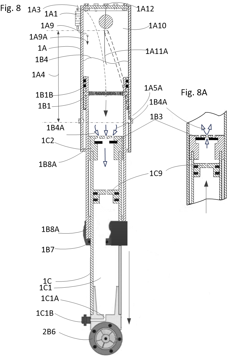 Fig. 8 & 8A — Oleo-Pneumatic Strut Mechanics
Principle 02
Rim-Driven Fluid Mechanics & Laminar Thrust
Embedding the motor directly into the peripheral rim structure leaves the center spoke area completely unoccluded, establishing an ideal axial fluid propulsion corridor.
- Dual-Duty Rotor Blades (2B1): Hydrodynamic blade profiles withstand high terrestrial torque loads while generating efficient axial-flow thrust when submerged.
- Stator Vane Rectification (2C2): Rigidly connecting the outer rim to the central spindle, stator vanes bear structural loads while straightening turbulent propulsive wash into laminar jet thrust.
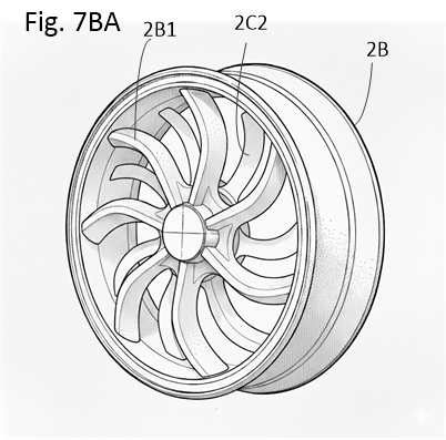 Fig. 7BA — Rim Impeller & Stator Vane Geometry
Principle 03
Hydrofoil Drag Reduction & Kinematic Transition
Transitioning from a displacement hull to hydrofoil-borne flight drastically alters the craft's hydrodynamic efficiency at cruising speed.
- Wetted Area Minimization: Lifting the main hull clear of the water surface eliminates wave-making resistance and reduces viscous skin-friction drag.
- Synchronized Winch Rigging: Unified chassis winches (9A1) and spreader bars (9A4) deploy drive assemblies and hydrofoil sets simultaneously, governed by fail-safe mechanical locking pins.
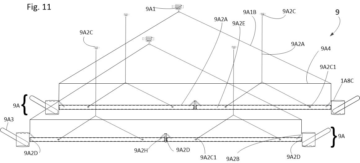 Fig. 11 — Winch-Actuated Foil Rigging