Unit 211, 1865 Osler St., Regina, SK, Canada S4P 1W1
Patent-Pending Amphibious Architecture

The Hydro-Terran Drive

An individual wheel-based drive mechanism delivering synchronized pneumatic suspension, high-speed terrestrial traction, water-jet marine thrust, and submersible operation using a single unified powertrain.

Unified Amphibious Powertrain

Eliminating dual-drivetrain weight and mechanical complexity through design science.

01

Terrestrial Stance

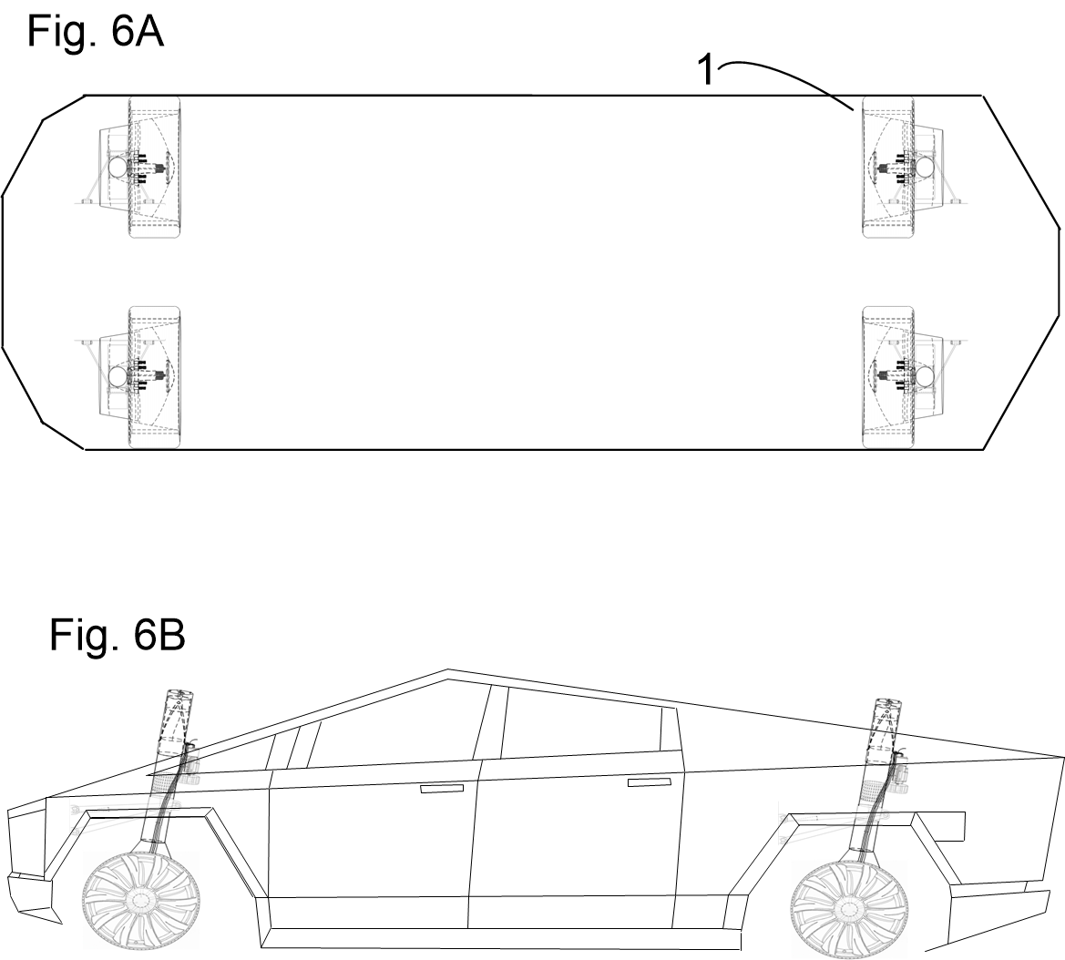
Operates as a high-performance EV wheel assembly with an in-wheel motor, steer-by-wire torque vectoring, motorcycle-fork shock raking, and active pneumatic cushioning.

02

Aquatic Pump-Jet

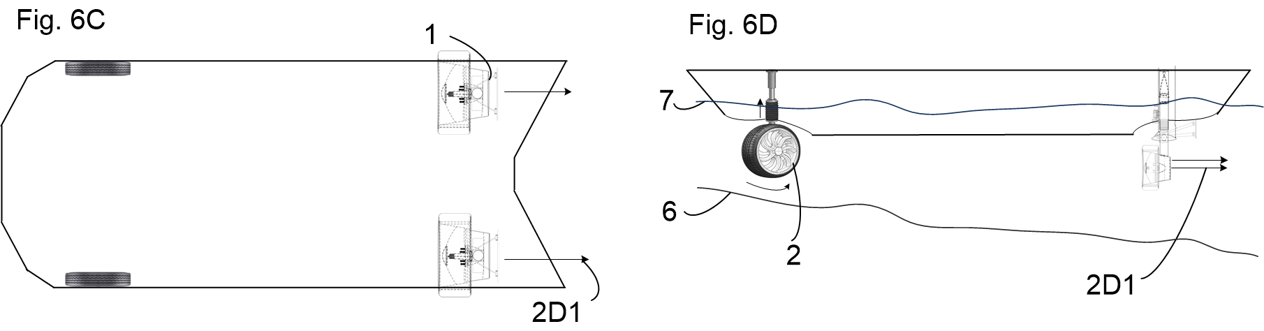
Rotates 90 degrees around its vertical suspension axis and descends into the waterline, converting custom wheel spokes into axial water-jet impellers.

03

Submersible Flight

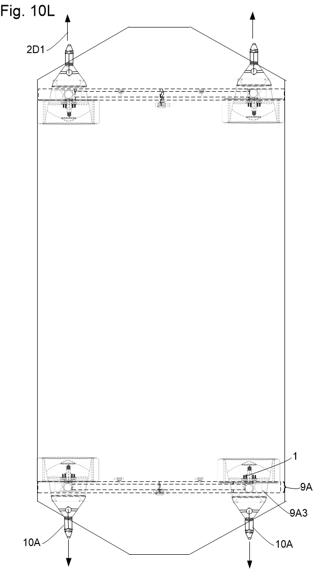
Simultaneously deploys incidence-controlled hydrofoils to slash hydrodynamic drag above water, or achieve full 3D pitch and roll control underwater.

IP Australia Provisional Application

Patent 2026907407

Invention: The Hydro-Terran Drive: An individual wheel-based drive mechanism that enables efficient and effective suspension and propulsion of suitably equipped vehicles on land, water, and underwater using substantially the same mechanisms.

  • Filing Reference: AMCZ-2616182054
  • Submission Date: 31/08/2026
  • Applicant: Robert Carpenter | BioShip Inc.
  • Core Novelty: Coaxial suspension rotation, spoke impellers, and synchronized hydrofoil sleeves.
Key Architectural Claims
• 3-Cylinder Coaxial Nested Suspension
• 90° Electromagnetic Engagement Pin Channel
• Spoke-Integrated Water-Jet Rotor Blades
• Synchronized Hydrofoil Deployment Assembly
• Emergency Firefighting / High-GPM Water Manifold

Engineering & Mechanical Systems

Three interconnected subsystems form the foundation of the Hydro-Terran drive architecture.

Subsystem 01

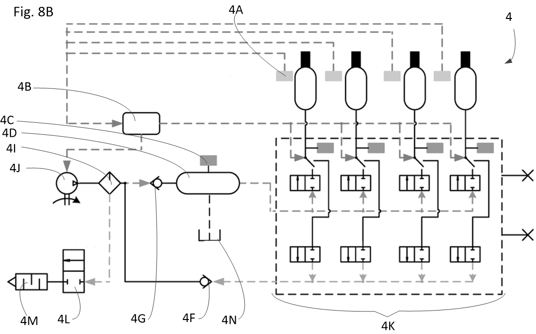
Tri-Cylindrical Pneumatic / Oleo Suspension

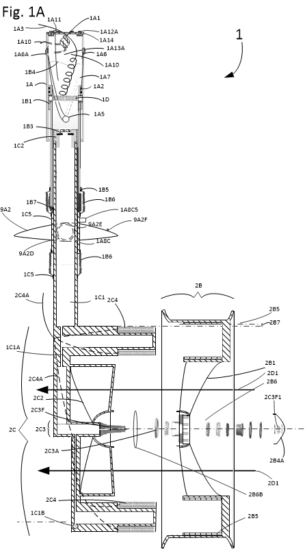
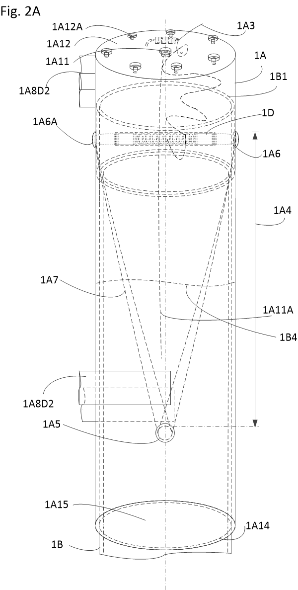
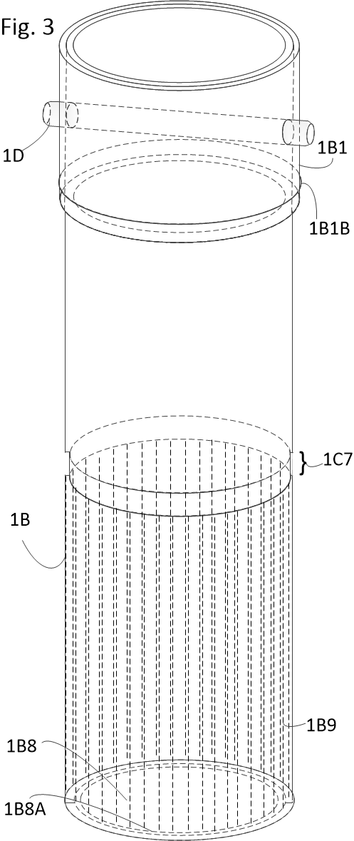
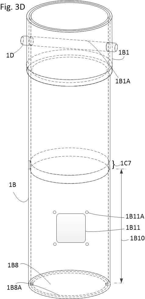
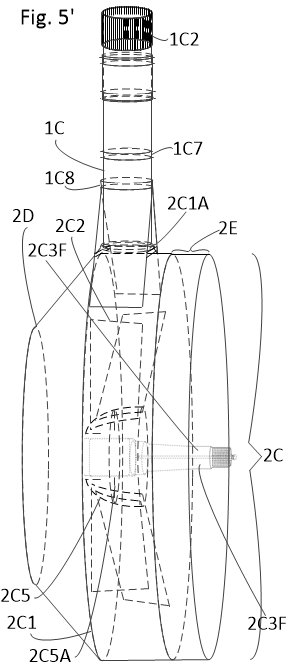
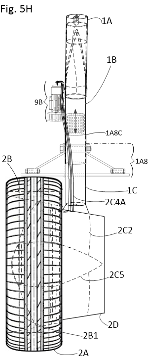
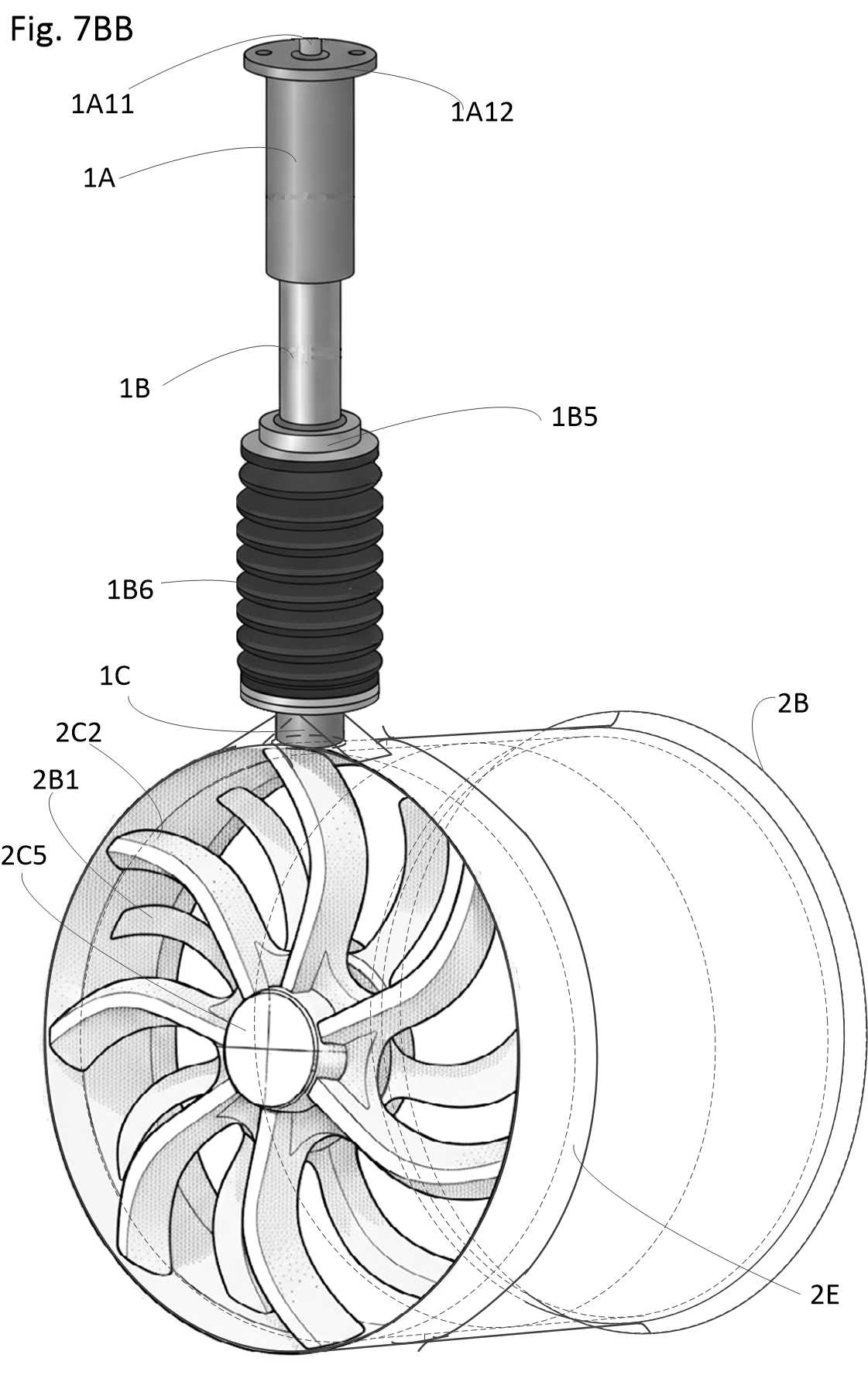
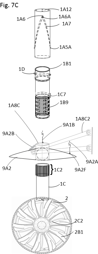
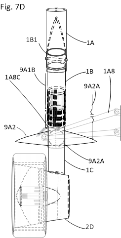
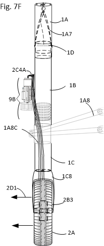
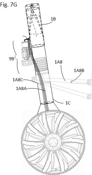
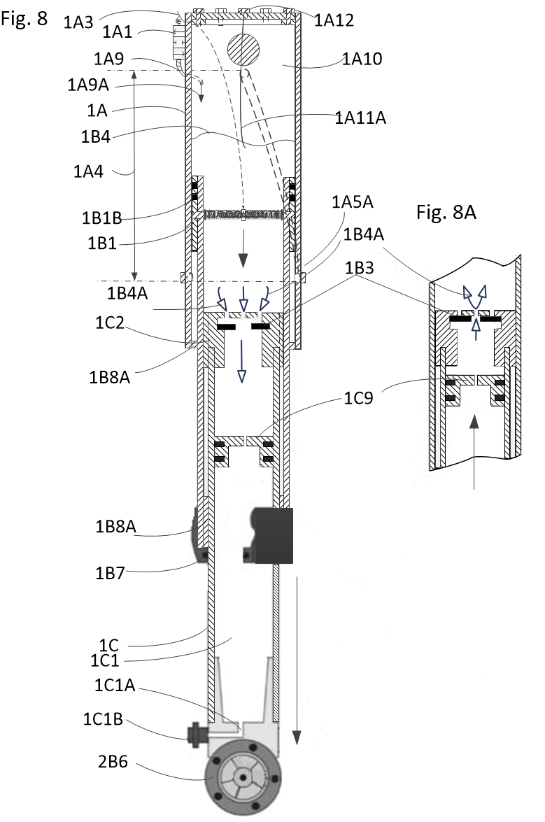
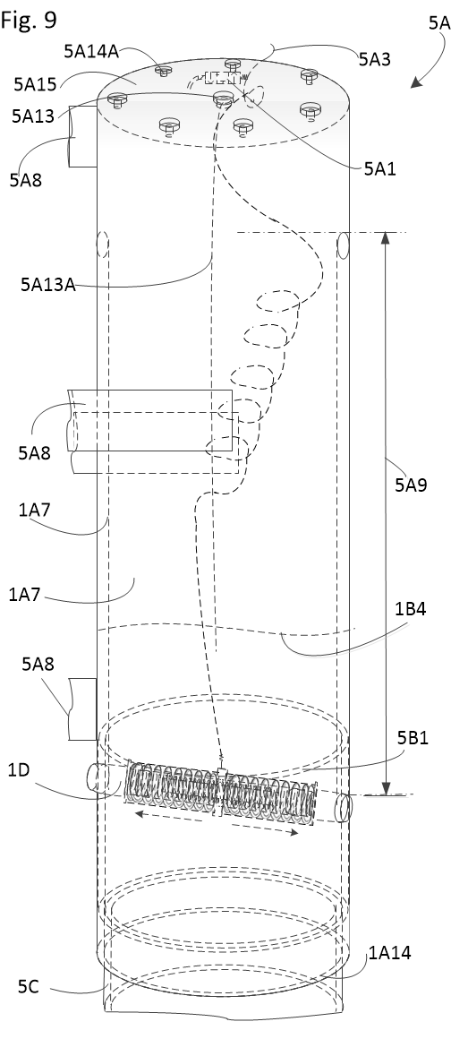
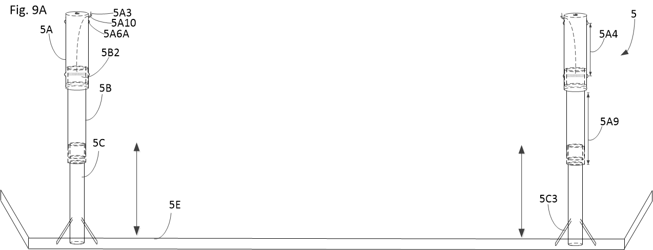
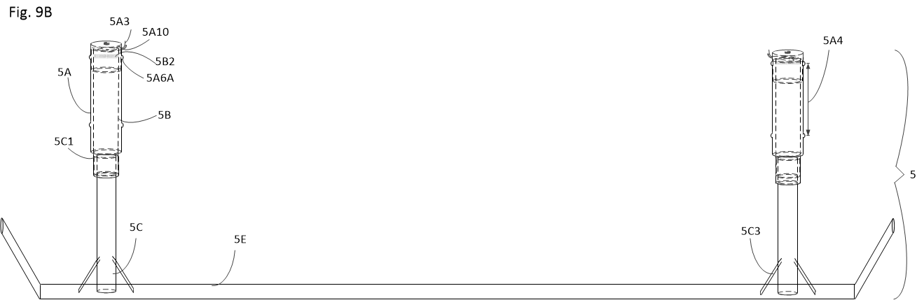
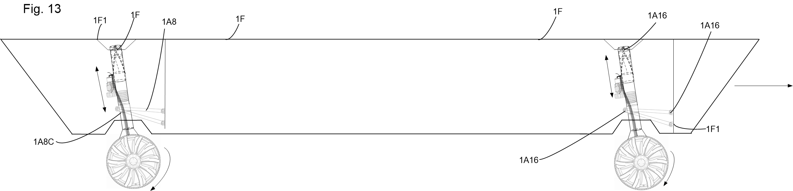
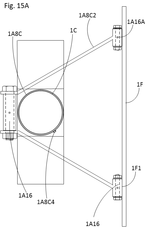
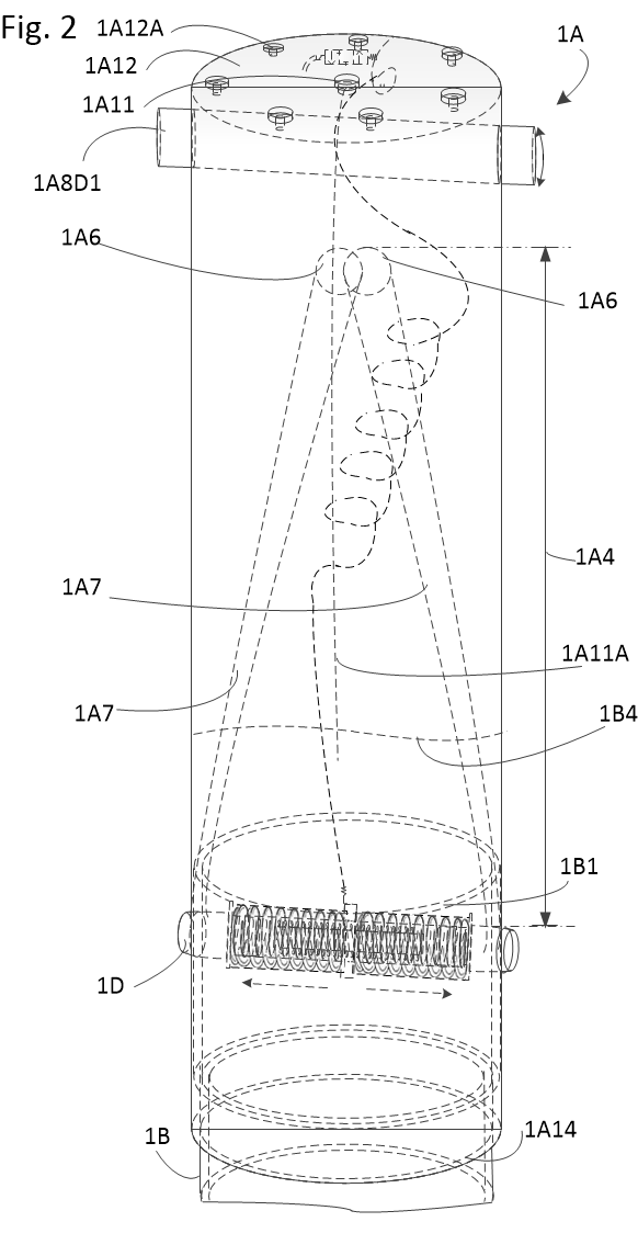
Three coaxial stainless-steel cylinders (Upper 1A, Middle 1B, and Lower 1C) provide variable pneumatic damping while functioning as the primary actuator for amphibious redeployment.

  • Upper Cylinder (1A): Houses internal spiral guide channels (1A7) cut to a depth of at least 1.5 mm, guiding vertical displacement and a 90° axial turn.
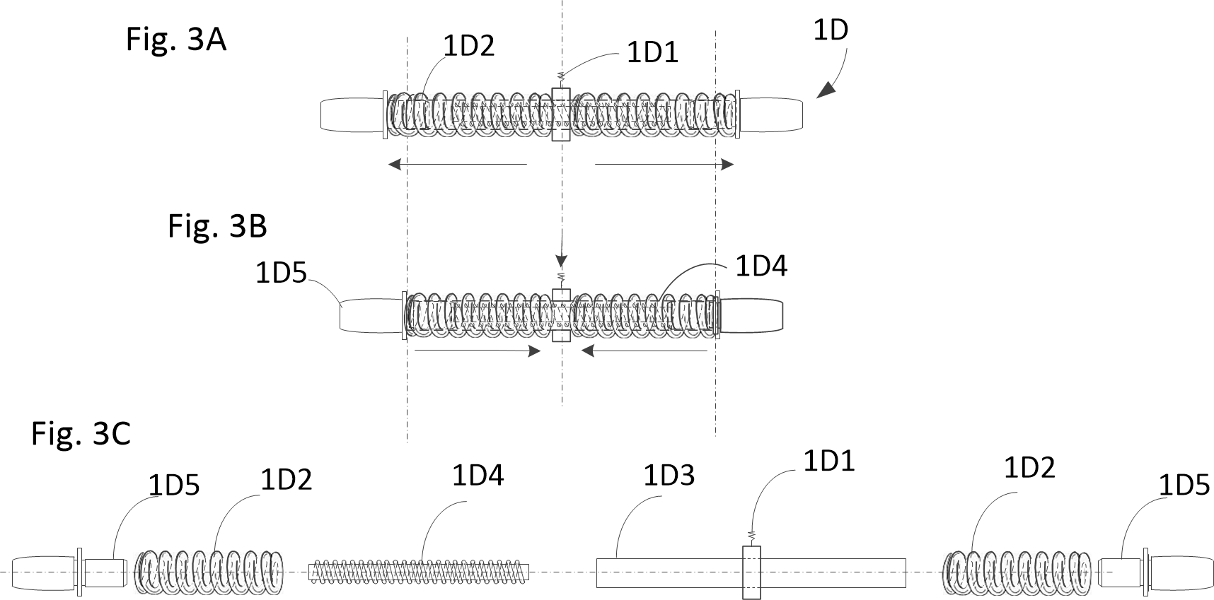
  • Dual-Ended Electromagnetic Pin (1D): Spring-extended (1D2) into upper land holes (1A6) or lower water holes (1A5). Solenoid energization retracts pin tips (1D5) to traverse guide channels.
  • Sealed Integrity: Flexible rubber bellows (1B6) with retaining rings (1B5, 1C5) protect oscillating slide joints against pressurized salt water and road grit.
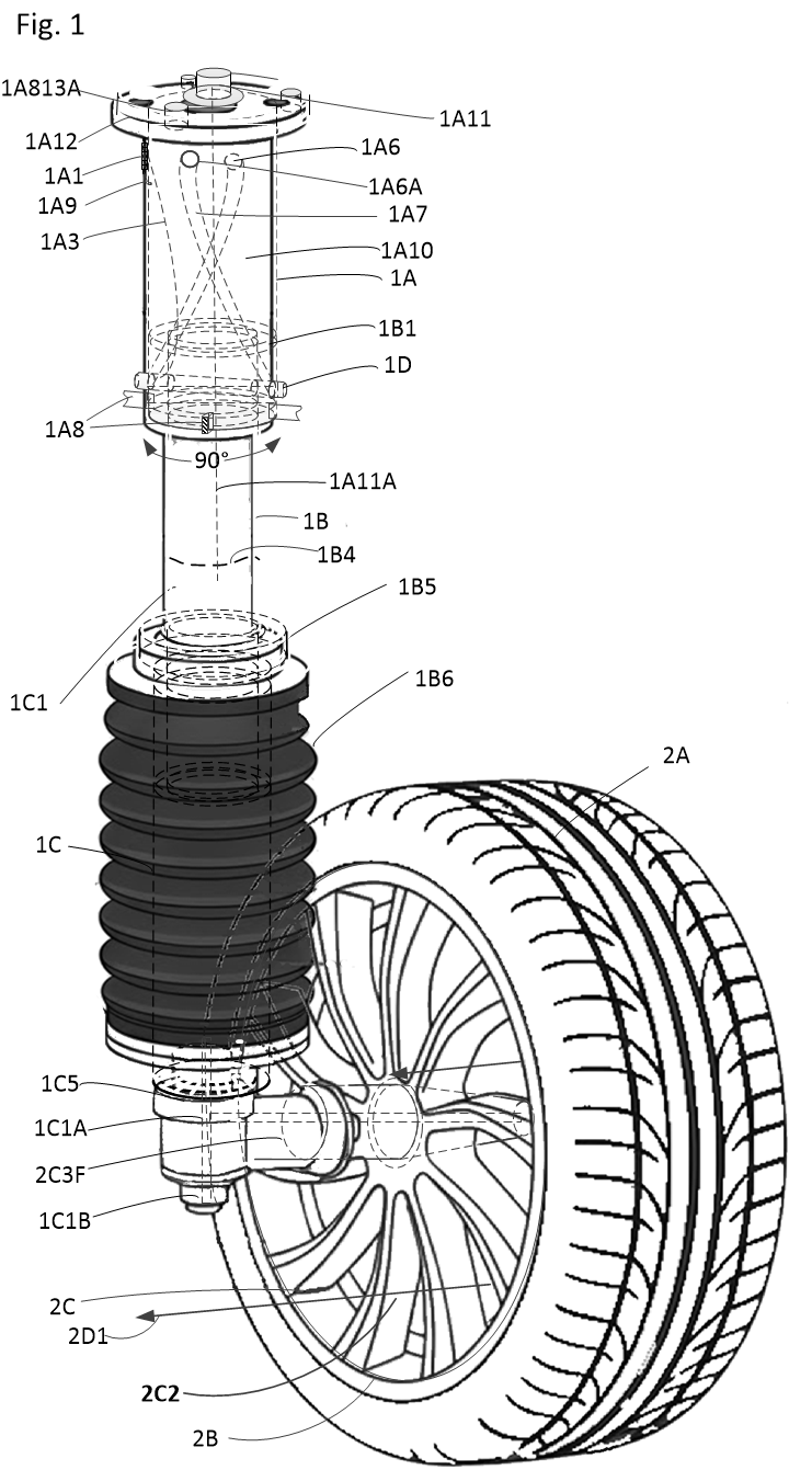
Fig 1 Suspension Assembly Fig. 1 — Full Drive & Suspension Assembly (Click to Enlarge)
Subsystem 02

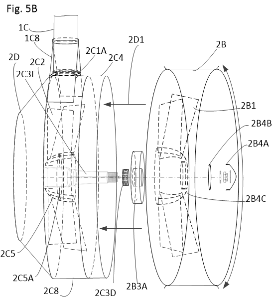
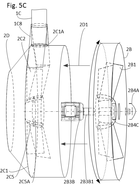
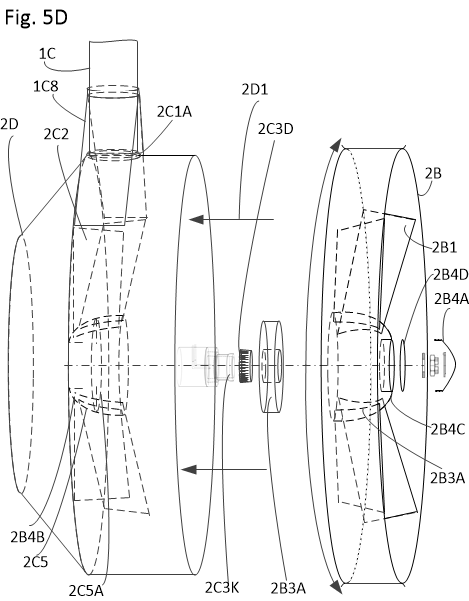
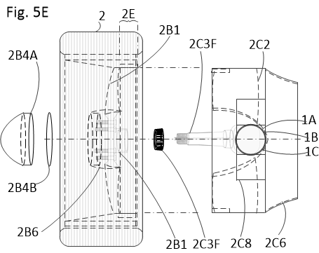
Dual-Mode Wheel / Pump-Jet Impeller

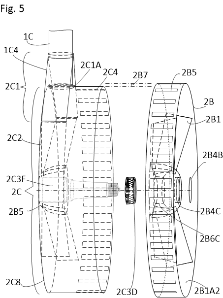
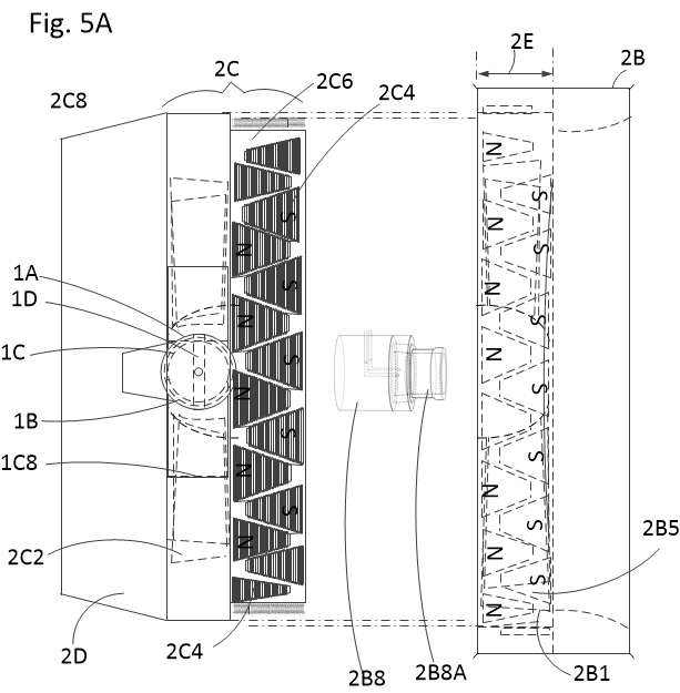
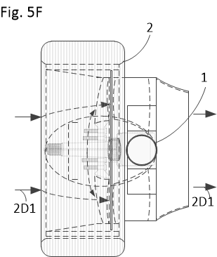
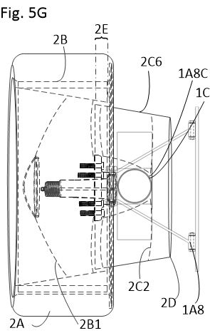
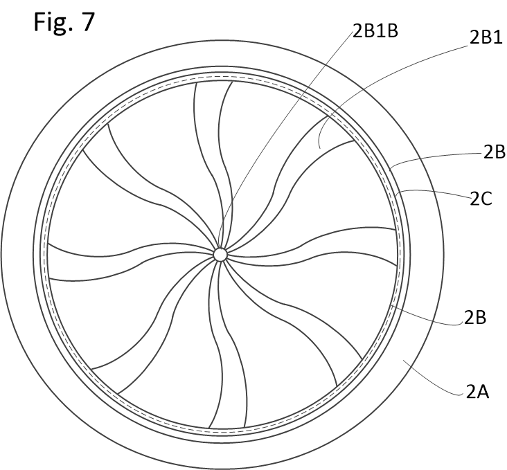
By integrating an axial flux or peripheral motor directly into the rim structure, the center spoke area functions as an unoccluded, high-throughput fluid propulsion corridor.

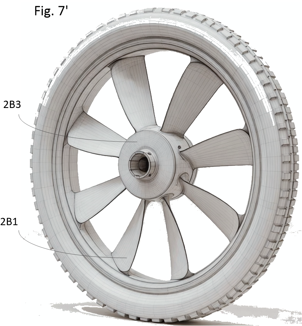
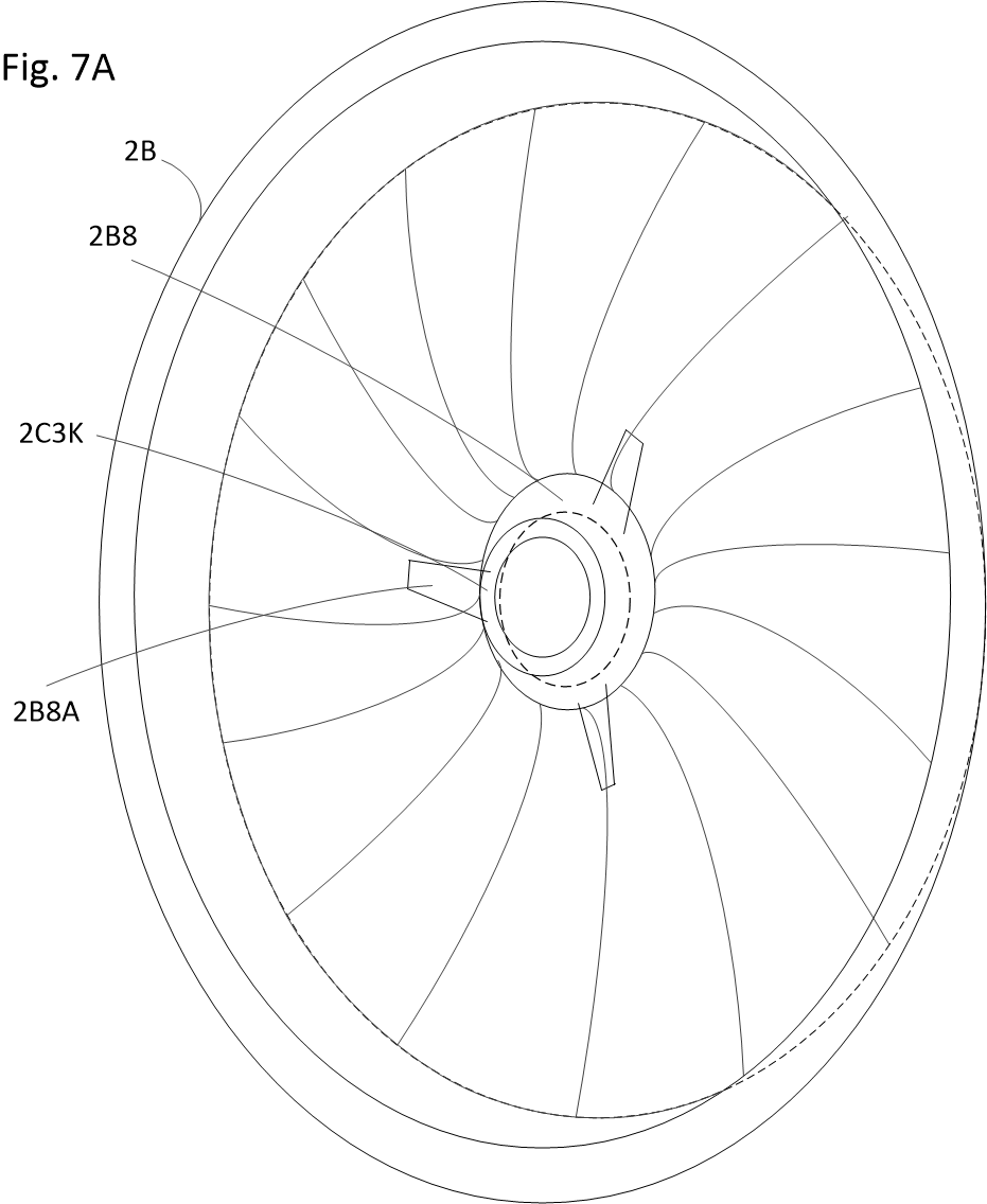
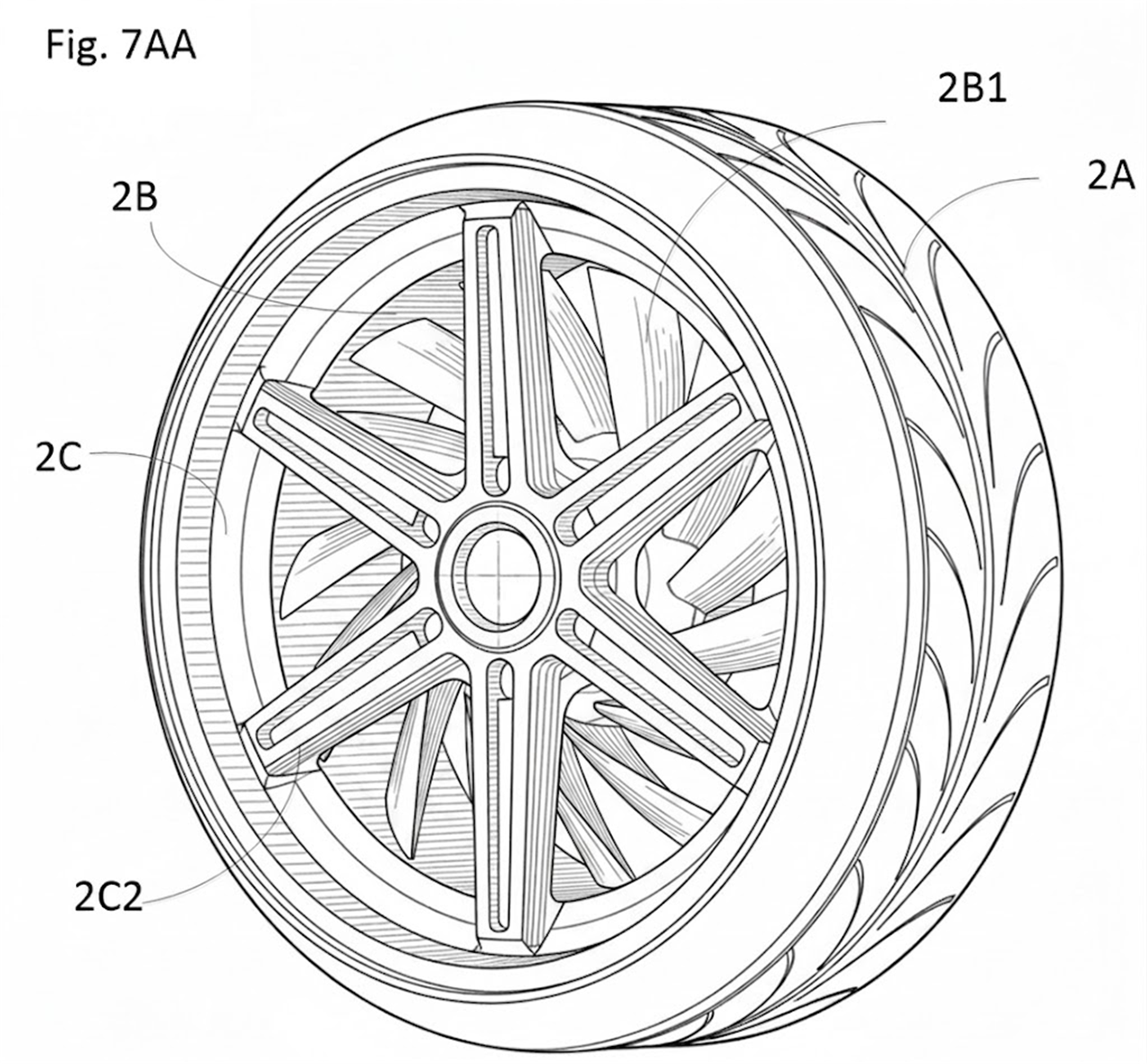
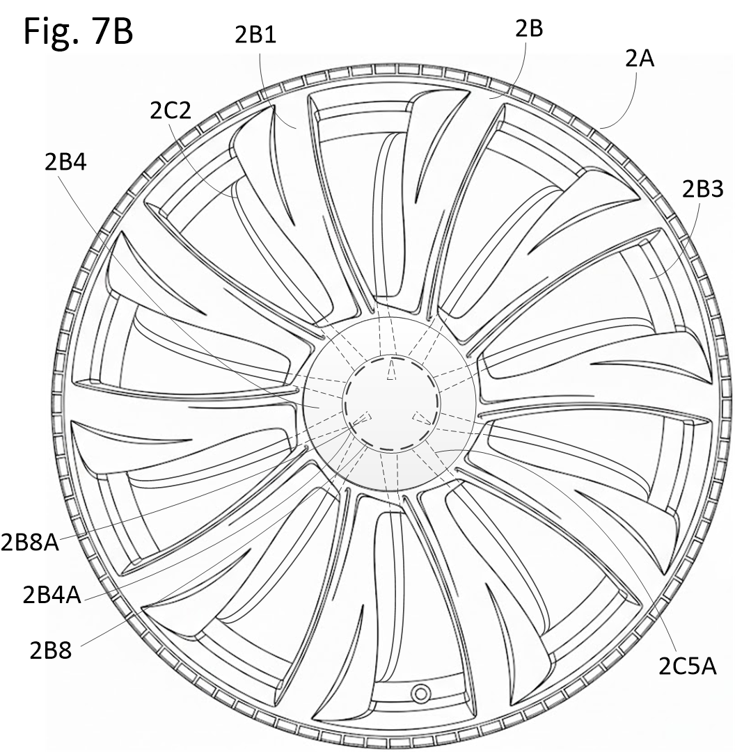
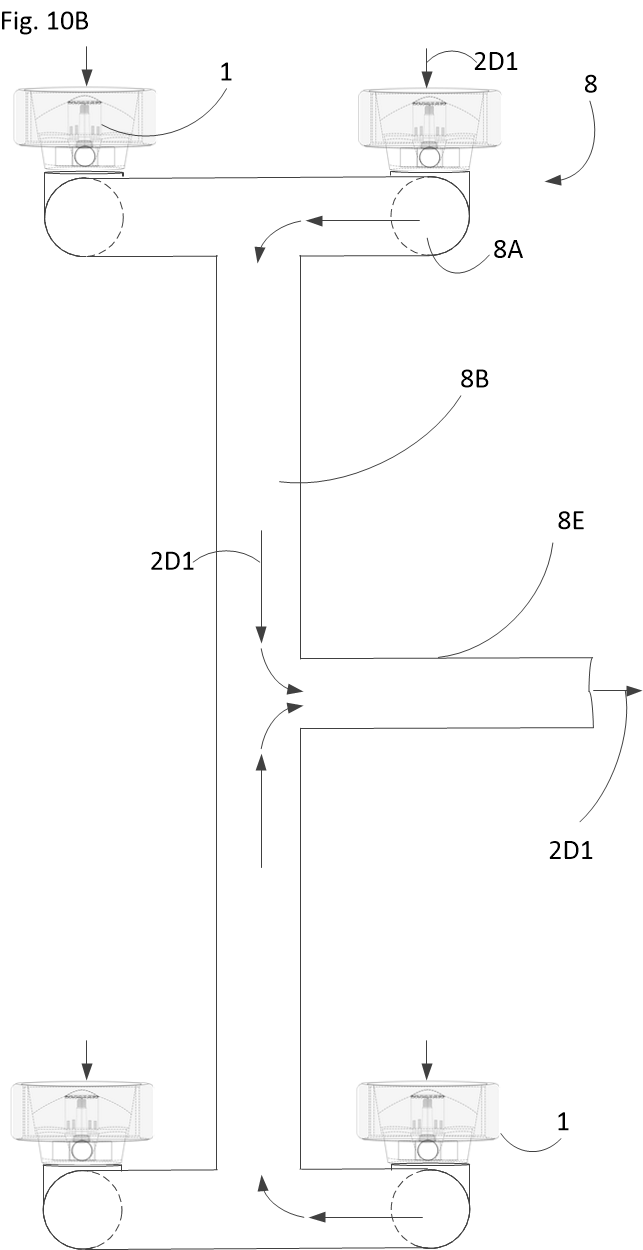
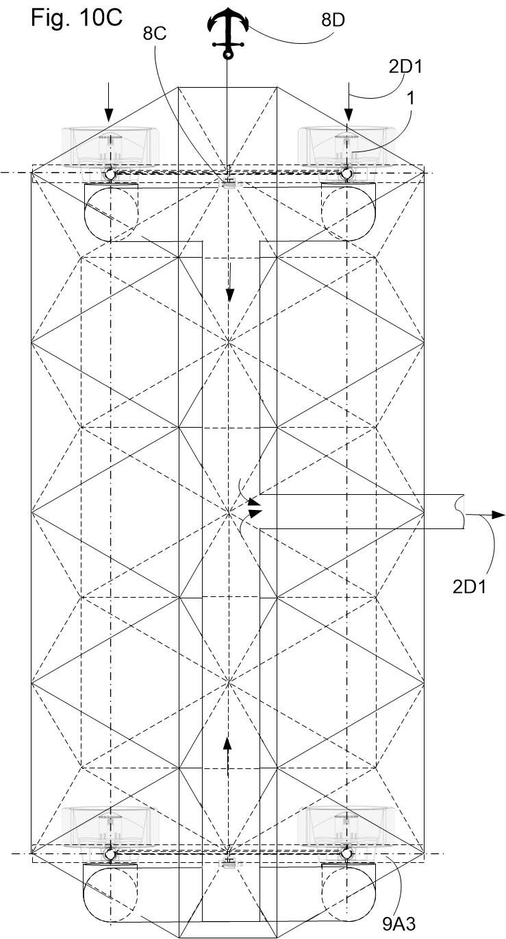
  • Rotor Blades as Structural Spokes (2B1): Hydrodynamic profiles carry vehicular road shock on land and generate powerful axial-flow thrust (2D1) when submerged.
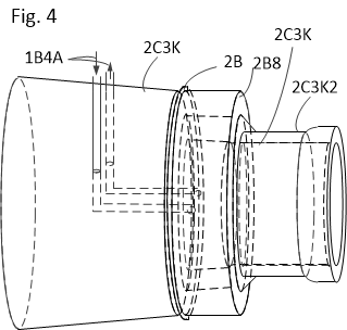
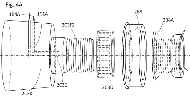
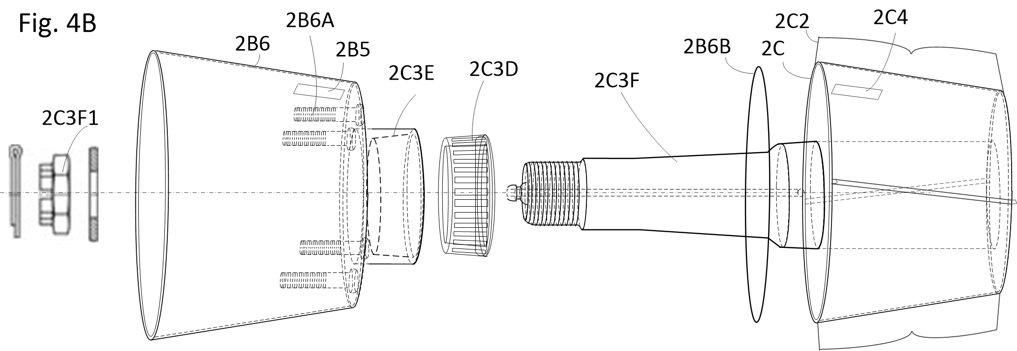
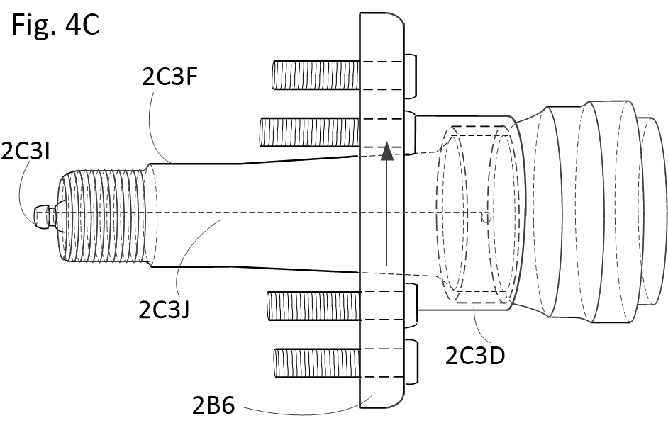
  • Angled Stator Vanes (2C2): Rigidly connect the outer rim (2C8) to the central spindle (2C3F), converting swirling propulsive wash into straight, laminar jet thrust.
  • Motor Adaptability: Accommodates peripheral magnetic arrays, compact axial flux motors (2B3A), radial flux motors (2B3B), and bilateral axle drives.
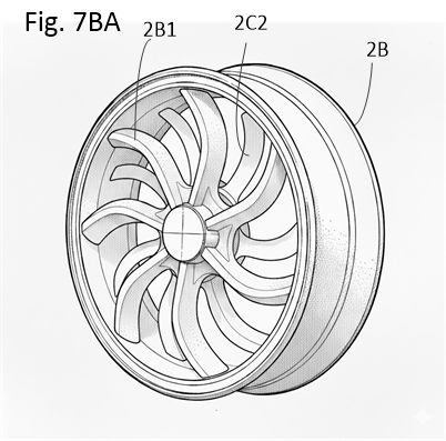
Fig 7BA Wheel Impeller Fig. 7BA — Wheel Rim / Water-Jet Impeller
Subsystem 03

Synchronized Hydrofoils & Steer-By-Wire

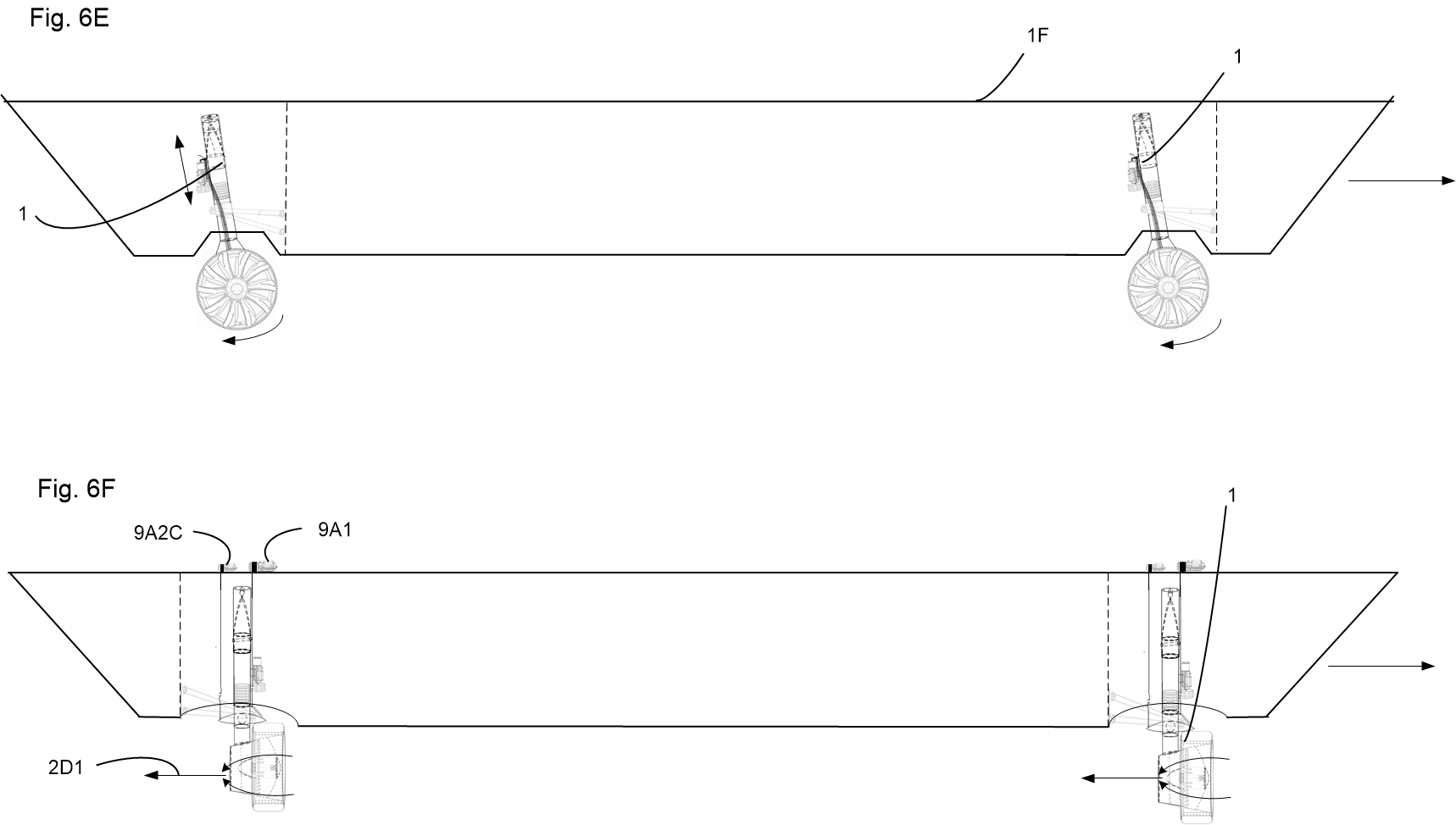
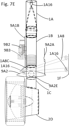
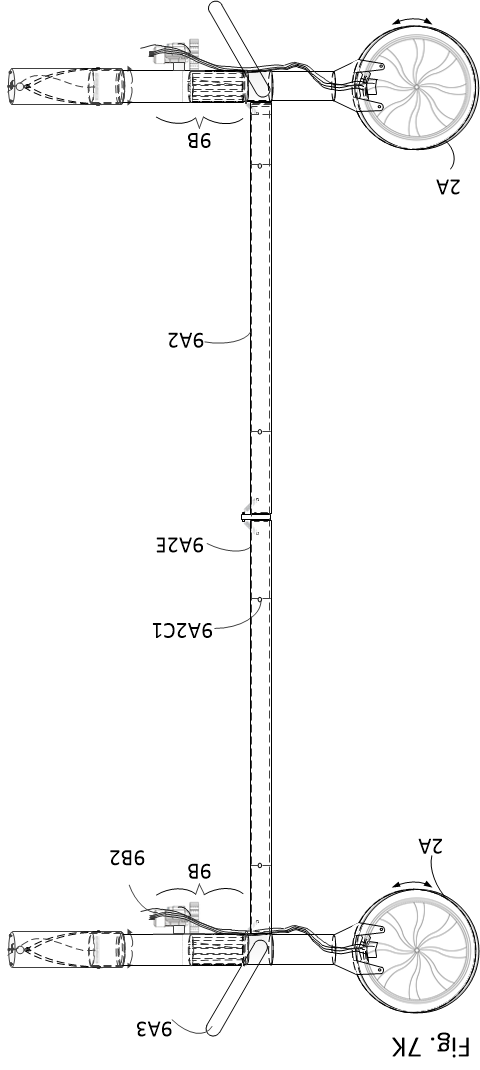
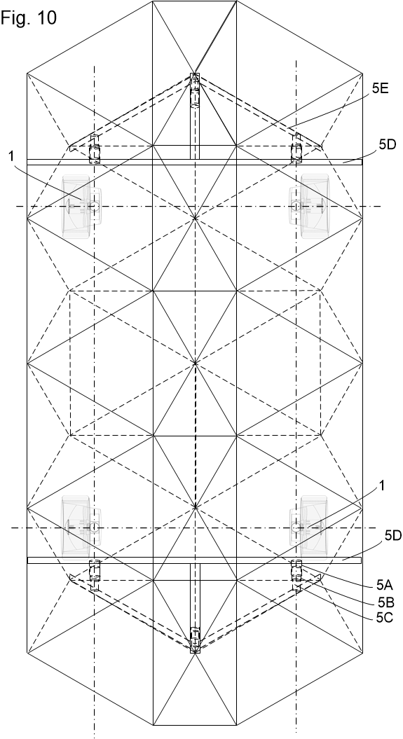
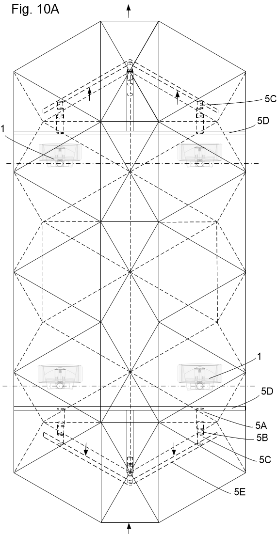
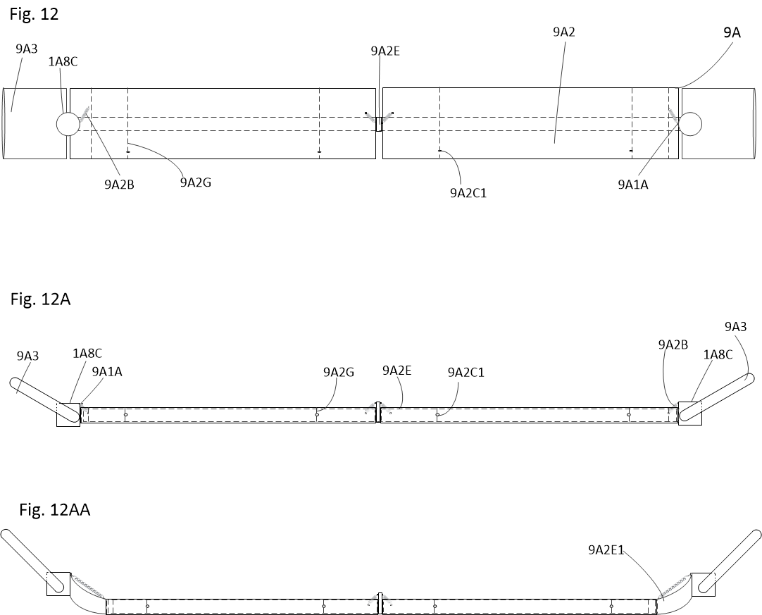
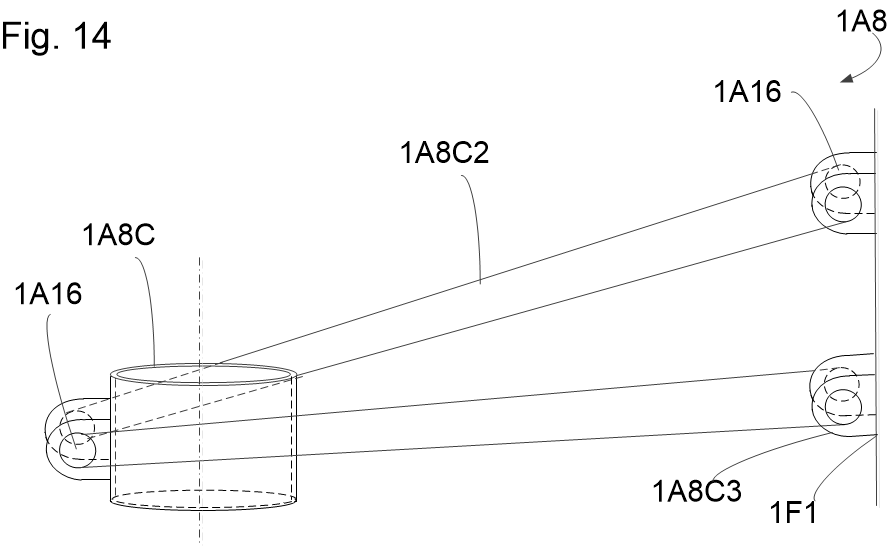
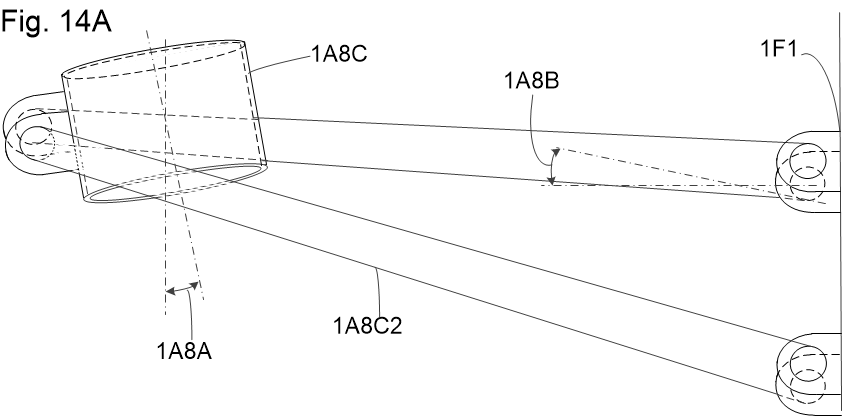
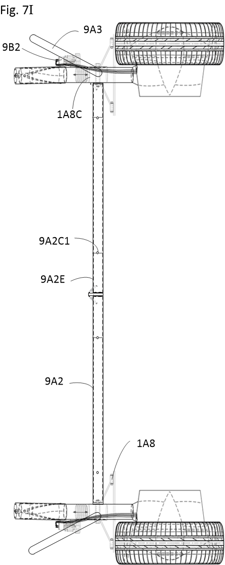
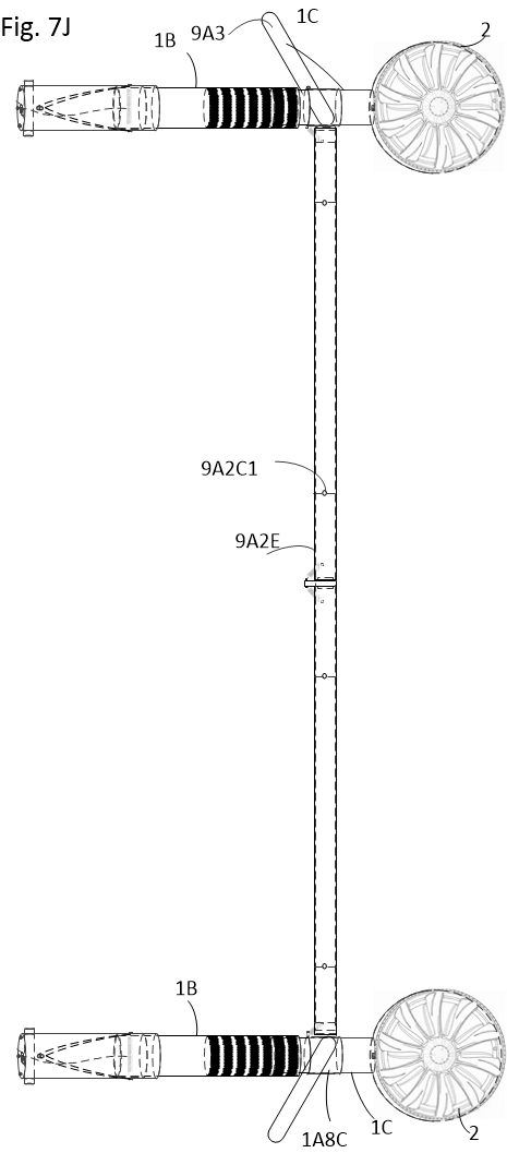
Connected directly to cylindrical sleeves on the lower suspension, front and rear hydrofoils deploy simultaneously with the wheel assemblies via unified chassis winches and spreader bars.

  • ~900x Drag Reduction: Lifts the vehicle hull clear out of the water surface, achieving highway velocities on open water with standard EV battery loads.
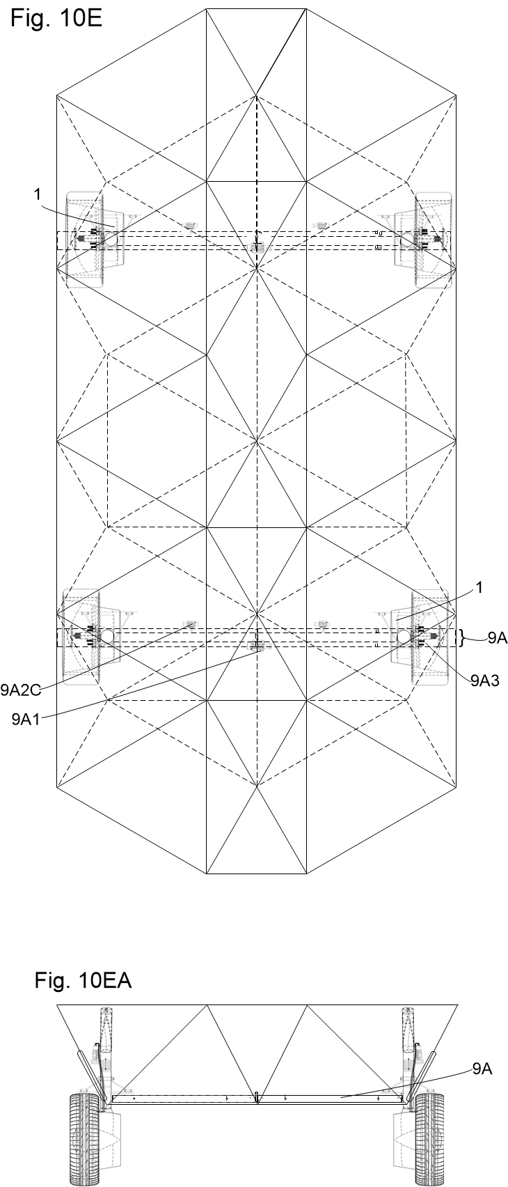
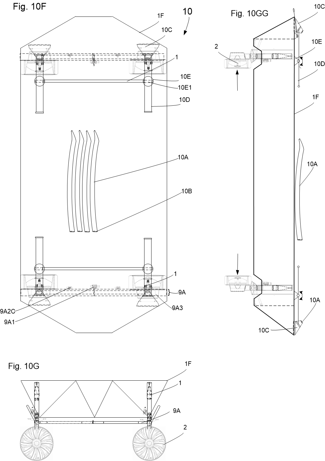
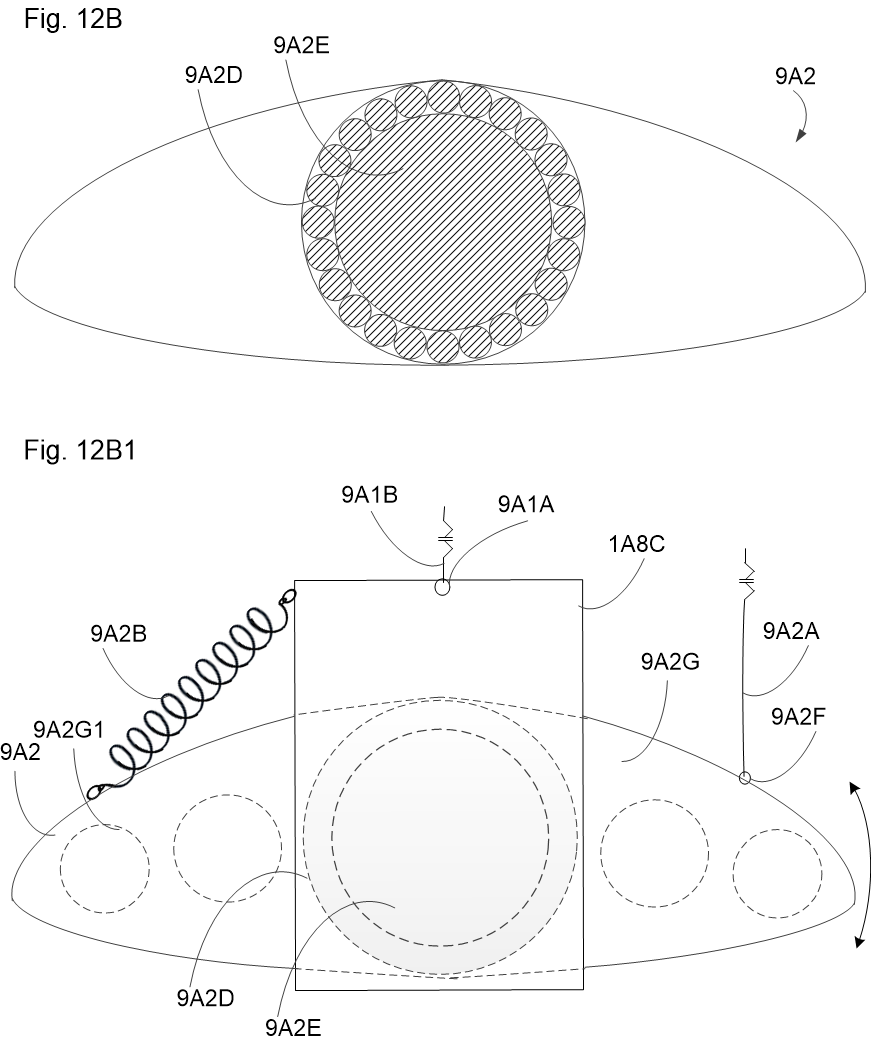
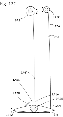
  • Dynamic Incidence Control: Foil winches (9A2C) and counteracting springs (9A2B) rotate foils around central shaft (9A2E) for banking, braking, and submarine depth control.
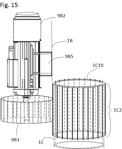
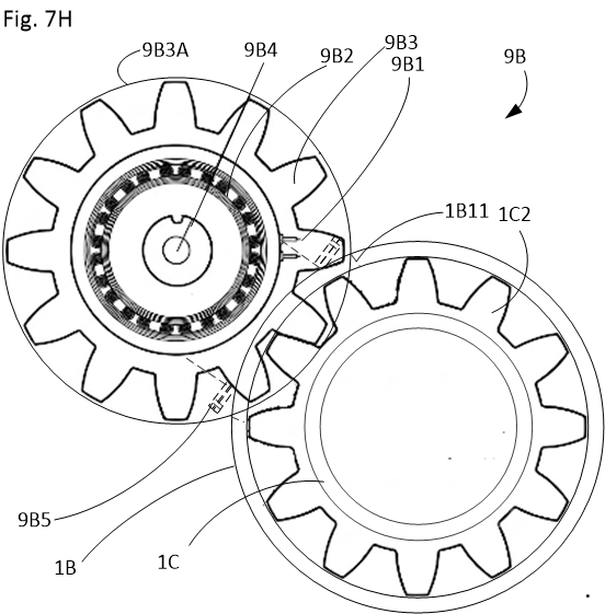
  • Continuous Steer Meshing: Steer-by-wire servo pinions (9B3) mesh through middle cylinder portal (1B11) into elongated geared piston (1C2) across full suspension stroke.
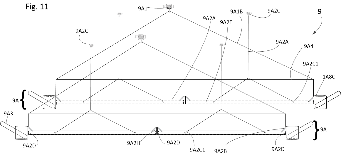
Fig 11 Deployment System Fig. 11 — Winch-Actuated Foil Rigging
Amphibious Transition Sequence

A pushbutton transition executed automatically via onboard ECU processor control.

1

Water Entry & Verification

Sensors verify craft buoyancy and depressurization of road loads across all four corners. Transition lockout prevents activation while in high-speed motion.

2

Electromagnetic Unlocking
Current energizes pin electromagnet 1D4, overcoming internal springs to retract pin tips 1D5 from upper locking holes 1A6 while remaining captured in guide channels 1A7.
3

Guided 90° Rotation & Descent

Deployment winches lower the lower cylinders and sleeves. Travel along the spiral channel grooves forces a precise 90° axial rotation and vertical descent beneath the keel.

4

Spring-Loaded Re-Locking

Upon reaching the lower holes 1A5, pin power is cut. Springs snap the pins into locking holes, rigidizing the assembly for thrust vectoring and hydrofoil flight.

Commercial & Tactical Applications

Multi-sector capabilities enabled by the Hydro-Terran drive architecture.

Wildfire Suppression & Irrigation

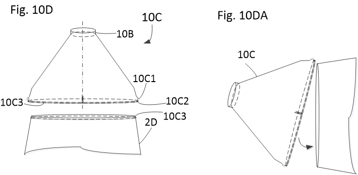
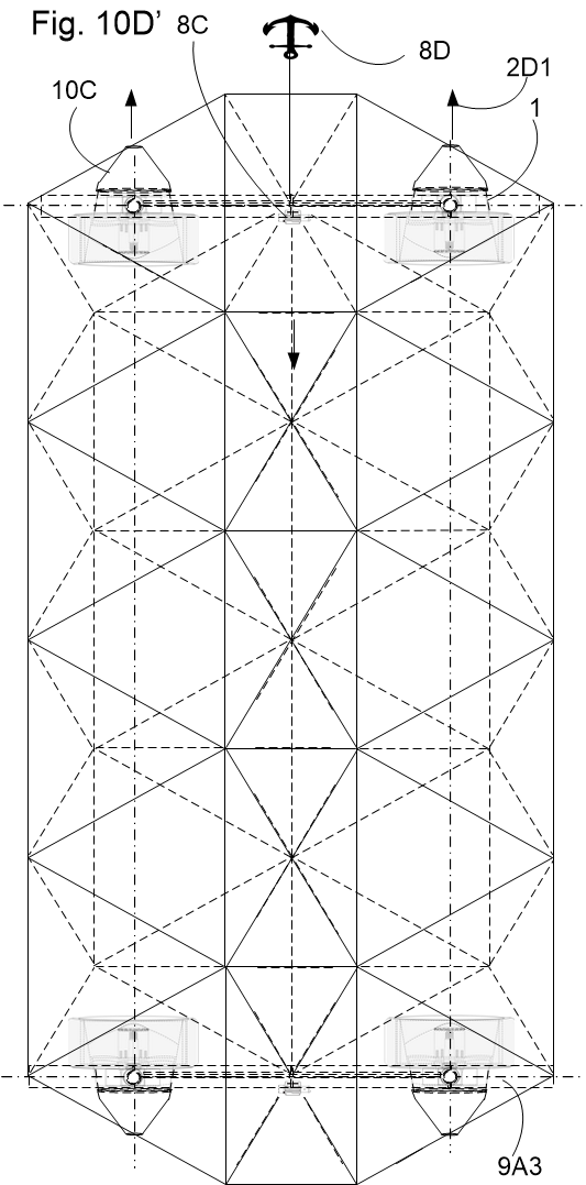
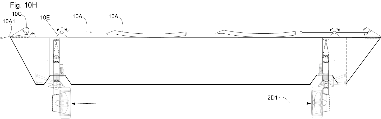
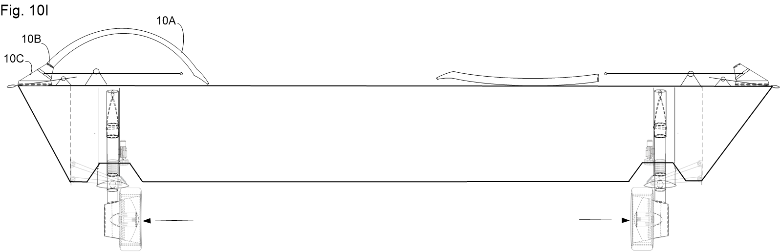
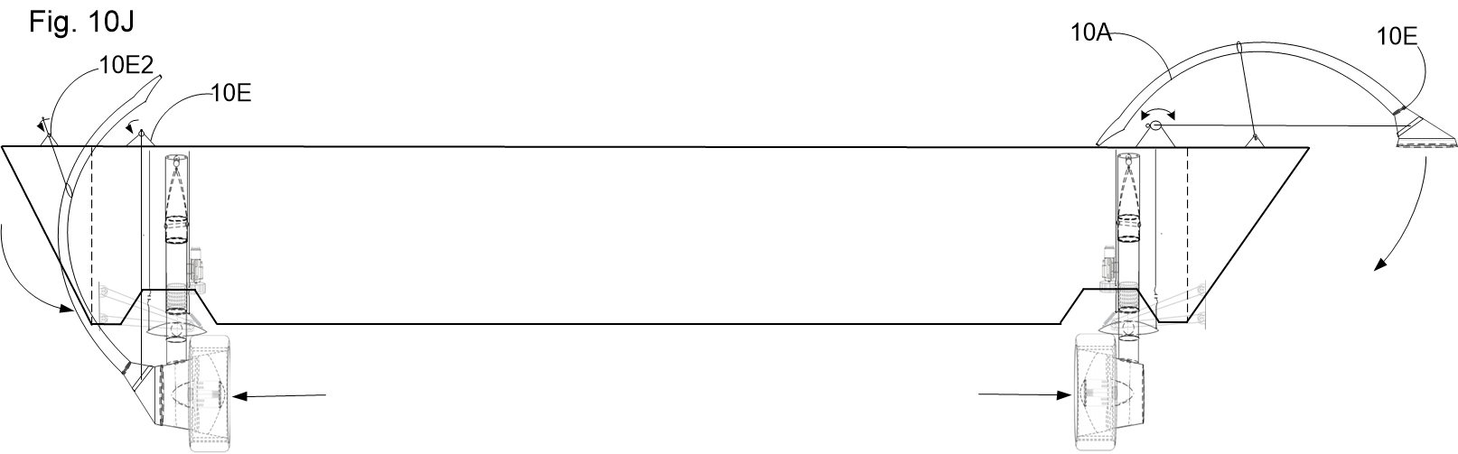
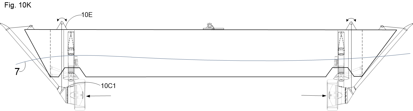
By attaching quick-connect Storz cam-lock adapters (10C) directly to the pump-jet nozzles, each in-wheel motor converts into a high-pressure, multi-thousand GPM water cannon parked directly in a lake or river.

Submersible & Defense Recon

In a watertight hull with active buoyancy cells, dynamic foil incidence control enables true submarine exploration, silent littoral approach, and 360-degree zero-radius maneuvering.

High-Speed Eco-Transit

Bypassing gridlock by utilizing waterways at highway speeds without water wakes or fuel burn, providing sustainable island, coastal, and remote northern transport.